
Designing plastic parts is a highly detailed engineering equation that must take into account the mechanical loads at the point of use, chemical contact, thermal shocks and the tolerance requirements of assembly. Beyond functional and structural expectations, the high-pressure entry of molten plastic into the mold cavity, molecular orientation and cooling dynamics directly determine the final strength of the part. Splitting a large and complex design into several smaller parts minimizes flow and cooling problems during molding. These parts can later be easily assembled by methods such as ultrasonic welding, snap-fit joints or screw fastening.
Why injection molding?
Plastic injection molding is the industry's most preferred process for high-volume production, from electronic components to automotive parts and medical disposables. Using multi-cavity molds, dozens of parts can be produced within seconds in a single cycle. High dimensional accuracy, flawless repeatability from shot to shot, low labor costs and the possibility of loss-free operation are the standout advantages of this method. Its biggest limitations are the high equipment and engineering cost of mold making and the difficulty of adapting the mold to design changes made later on.
Material selection: amorphous and semi-crystalline polymers
All thermoplastics and many elastomers can be used in this method. When selecting a material, the structural differences between amorphous and semi-crystalline polymers must always be taken into account. Amorphous materials such as polycarbonate or ABS shrink equally in all directions in the mold, whereas semi-crystalline materials such as polypropylene or polyamide shrink at different rates in the flow direction and perpendicular to the flow. If these shrinkage differences are not calculated correctly, the part coming out of the mold will not meet the expected dimensions.
The injection press and clamping tonnage
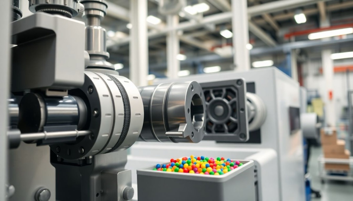
An injection press consists of a heated barrel that melts the granular material, a reciprocating screw that pushes the material forward, and a clamping unit that keeps the mold closed under pressure. The ideal clamping tonnage is calculated by multiplying each square inch of the part's projected area on the mold surface by a force of two to eight tons. Very stiff plastics need higher injection pressure to fill the mold, which in turn requires a much higher clamping tonnage to prevent the mold from opening. The length-to-diameter ratio of the screw in the barrel is a critical engineering parameter for homogeneous melting of the material and complete mixing of the color pigments.
Mold materials
The material used to make the molds at the heart of production is chosen according to the target production volume. Fully hardened steel molds are heat-treated to a hardness of 50 to 60 Rockwell. In projects that will run millions of shots, they provide maximum resistance to wear and high pressure. Pre-hardened steel molds have a hardness of 38 to 45 Rockwell and offer a cost advantage for lower-volume production or for very large parts. High-grade aerospace aluminum molds transfer heat much faster than steel. Thanks to this rapid cooling capability, cycle times drop dramatically and hundreds of thousands of parts can be molded in a much shorter time. At the bottom of thin cores and in blind spots inside the mold that cooling water cannot reach, beryllium copper alloy inserts are used to absorb and remove heat instantly.
| Mold material | Hardness | Key property | When to choose it |
|---|---|---|---|
| Fully hardened steel | 50–60 HRC | Maximum resistance to wear and high pressure | Projects that will run millions of shots |
| Pre-hardened steel | 38–45 HRC | Cost advantage | Lower-volume runs or very large parts |
| Aluminum (aerospace grade) | — | Transfers heat much faster than steel, shortening cycle time | Molding hundreds of thousands of parts in a short time |
| Beryllium copper alloy | — | Absorbs and removes heat instantly | Thin core bottoms and blind spots that cooling water cannot reach |
The production cycle step by step
The production cycle begins when granular plastic is fed from the hopper into the barrel and melts under the frictional heat generated by the rotating screw. Once the clamp closes the mold, the screw surges forward and injects the molten plastic into the mold cavity at very high speed. After the part fills the mold, hold pressure is applied to compensate for the volumetric shrinkage that occurs during cooling by packing extra material into the cavity. When the core temperature of the plastic drops below its solidification point, the mold opens and the ejector pins push the part out.
- MeltingGranules are fed from the hopper into the barrel and melt under the frictional heat of the rotating screw.
- InjectionThe clamp closes the mold and the screw forces the melt into the mold cavity at high speed.
- Hold pressureThe volumetric shrinkage that occurs during cooling is compensated with extra material.
- Cooling and ejectionOnce the core temperature drops below the solidification point, the mold opens and the ejector pins remove the part.
Special molding technologies
Beyond the conventional method, many special molding technologies have been developed to meet the needs of the industry. Gas- and water-assisted injection, which hollows out the interior to reduce part weight; multi-component molding, in which two materials of different color or hardness are molded at the same time; liquid silicone rubber injection; in-mold labeling and decoration; micro-injection; low-pressure structural foam molding; and thin-wall molding with wall thicknesses below one millimeter are all widely used in the industry.
Internal stresses
The high pressure and narrow mold channels the plastic is subjected to during molding cause the long polymer chains to bend and break. These strains in the molecular structure are trapped inside the mold and create internal stresses in the part. In the field, these stresses cause the part to crack spontaneously or lose its resistance to chemicals. The only way to minimize internal stresses is to avoid sharp corners in the design entirely and to make all thickness transitions with smooth radii.
Runner and gate design
The gate, the point where molten plastic enters the mold, is one of the most sensitive areas determining part quality. Gate type and location determine the part's mechanical strength, cosmetic appearance and packing density. In addition to manual gates that require operator or robot intervention, tunnel and banana-type submarine gates that break off automatically when the mold opens are frequently preferred. In hot runner systems, instead of freezing in a cold runner, the plastic is injected through a heated nozzle in direct contact with the mold surface. The gate should always be located at the thickest section of the part. This way the melt advances toward the thinner sections without losing pressure and no air voids are left inside the mold. In materials with a high shrinkage rate, high stress builds up in the gate area, so the gate must be placed away from critical strength points.
Wall thickness
Wall thickness is the most important criterion determining part cost and cooling time. During molding, cooling time increases in proportion to the square of the wall thickness. For this reason, the target should always be the thinnest wall that meets the mechanical requirements. Depending on the product, the wall thickness of injection-molded parts can range from half a millimeter to four millimeters. The golden rule of design is that wall thickness must be completely uniform at every point of the part. Thick sections cool late, thin sections solidify early. Different cooling rates force the material to shrink at different rates, and the part warps and loses its shape the moment it leaves the mold. If a change in thickness is unavoidable by design, the transition should be made gradually and tapered, at a ratio of one third.
Draft angle
For the part to be released from the mold without scratching or friction, a draft angle must be applied to all vertical surfaces in contact with the metal. Surfaces at right angles create a vacuum effect during ejection, and as the ejector pins push the part out they cause stress whitening and deformation on the surface. A taper of at least one to two degrees should be left on all vertical surfaces. If an aesthetic pattern or texture is to be used on the mold surface, an extra one and a half degrees should be added to the standard draft angle for every one thousandth of an inch of texture depth, to prevent the part from catching on the texture. In deep core areas, angles of three degrees ensure safe release from the mold.
Sink marks, ribs and bosses
During flow in the mold, the interior of thick sections is insulated from the outer surface, so it cools later and shrinks by creating a vacuum effect from the outside inward. This internal shrinkage leads to undesirable depressions, in other words sink marks, on the outer surface of the part. To prevent sink marks, the wall thickness of the support ribs used to increase the part's strength and of the screw seats called bosses must never exceed sixty percent of the thickness of the main wall they are attached to.
| Design topic | Rule | Why? |
|---|---|---|
| Wall thickness | 0.5–4 mm; uniform at every point of the part | Different cooling rates cause warpage |
| Thickness transition | If unavoidable, at a 1/3 ratio, gradual and tapered | Abrupt transitions create internal stress and warpage |
| Draft angle (plain surface) | At least 1–2° | Prevents vacuum effect, stress whitening and deformation |
| Draft angle (textured surface) | +1.5° for every 0.001 in of texture depth | The part releases without catching on the texture |
| Draft angle (deep core) | 3° | Safe release from the mold |
| Rib and boss wall thickness | At most 60% of the main wall | No sink marks on the surface |
| Gate location | Thickest section of the part | The melt advances without losing pressure, no air voids remain |
Parting line and venting
The surfaces where the moving and fixed halves of the mold meet are called the parting line. When designing the part, the flow direction of the melt should always be planned toward these parting surfaces. As the mold fills rapidly, the only place the air inside can escape is through the microscopic vent channels cut into these parting surfaces. If flow planning is done incorrectly and air becomes trapped in a blind spot of the mold, it reaches a high pressure, as in a diesel engine, ignites and leaves brown burn marks at the ends of the plastic part.
Cooling: about 70% of the cycle
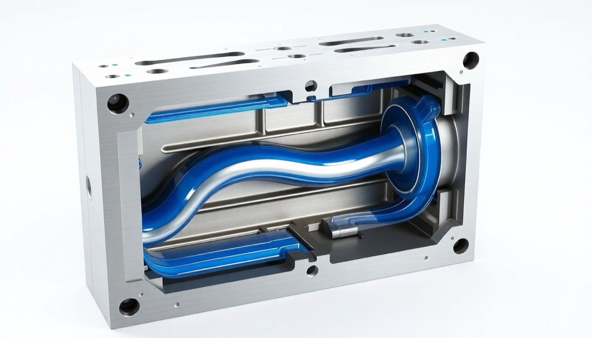
The cooling phase makes up approximately seventy percent of the injection cycle. In conventional molds, cooling channels are simply straight lines drilled into the steel and cannot cool every point of parts with complex geometries evenly. Today, conformal cooling channels produced with metal 3D printing technologies trace curved paths inside the mold steel that follow the shape of the part exactly. By removing heat completely uniformly from every point of the mold, this technology prevents part warpage and shortens cycle times by up to forty percent, radically reducing production costs.
Surface finishing
The cosmetic appearance and light transmission of the molded part are determined by the international surface finish standards applied to the mold steel. For surfaces requiring optical clarity or a mirror gloss, high-level polishing with diamond pastes is essential. For surfaces where a matte, rough or leather texture is desired, standardized texture depths are achieved by EDM or chemical etching methods. The most critical scientific rule not to be forgotten in design is that as the roughness of the mold surface increases, the draft angle given to the part to overcome friction must also be increased mathematically.
Common injection molding defects
During injection molding, many physical defects arising from mold design or process conditions can occur. Flash is the overflow of plastic out of the mold due to insufficient clamping force or an injection speed exceeding the limits of the machine. A short shot is the failure of the mold to fill completely because the barrel temperature is too low or air trapped in the mold prevents the plastic from advancing. Weld lines are weak joining lines formed when melt fronts that flow around obstacles in the mold and meet again cannot fuse completely because of the drop in temperature. Silver streaks or splay indicate that the plastic was not dried sufficiently before production and that the moisture inside evaporated in the mold, damaging the surface. Burn marks occur when the air in the mold cannot be vented and is compressed under pressure, burning the plastic. Voids are structural cavities formed inside the part when the material is drawn toward the center in thick sections or when hold pressure is cut off too early.
| Defect | What does it look like? | Cause |
|---|---|---|
| Flash | Plastic overflows out of the mold | Insufficient clamping force or injection speed beyond the machine's limit |
| Short shot | The mold does not fill completely | Low barrel temperature or trapped air preventing the melt from advancing |
| Weld line | Weak joining line | Melt fronts flowing around an obstacle cool and cannot fuse completely |
| Silver streaks / splay | Silvery streaks on the surface | Material not dried sufficiently; moisture evaporates in the mold |
| Burn mark | Brown marks at the ends of the part | Air cannot be vented, is compressed under pressure and burns the plastic |
| Void | Structural cavity inside the part | Material is drawn toward the center in a thick section or hold pressure is cut off too early |
Smart production cells
Modern plastic injection facilities are not just mechanical presses; they are smart production cells equipped with sensors, robotic systems and data analytics. Sensors that measure melt viscosity in the barrel, cavity pressure and cooling water temperature within milliseconds form closed-loop systems that autonomously adjust the machine's hold pressure and injection profile. When the mold opens, the parts are picked precisely by robot arms and placed in cooling fixtures to prevent temperature differences. Camera-assisted artificial intelligence systems instantly detect microscopic flash, incompletely filled areas or color deviations on the part, ensuring flawless production.
Design for assembly
Plastic part design does not end the moment the product leaves the mold; the assembly operations that determine how the parts will be joined to one another must also be included in the design. Weld joints added to the design allow two plastic parts to be melted together at the molecular level and joined in a leak-tight manner. When designing snap-fit hooks, the flexural properties of the material must be calculated to guarantee that the hook locks without breaking. In bosses where metal screws will be fastened into the plastic, the correct outer diameter thickness must be left to absorb the hoop stress the screw will create, and a radius must always be added at the base of the boss to prevent cracking.
Mold flow analysis
Advanced mold flow analysis software digitally simulates the behavior of the molten plastic before any steel is cut. Air traps, sink mark risks and weld line locations are identified at the design stage, preventing costly mold revisions. A plastic part designed in accordance with engineering rules runs smoothly on the production line, is easy to assemble and extends the commercial life of the project.
Let's choose the right protection package for your project together
Find the additives that suit your needs with our product selector, or consult our laboratory directly.